What is a potentiometer? A potentiometer is an adjustable voltage divider.
The basic components of all potentiometers include a resistive element or track and a sliding contact known as the wiper. Some potentiometers feature an output signal track, while in others, the wiper is directly connected to the output signal.
The wiper creates a short circuit between the resistive track and the signal track, allowing the potentiometer to divide the supply voltage proportionally to the wiper’s position along the sensor.
Potentiometers come in a wide variety, but they can be categorized into three main technologies:
- Wire-wound potentiometer
- Conductive plastic potentiometer
- Hybrid potentiometer
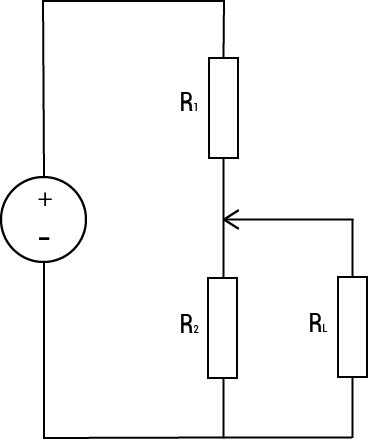
Image to the left is a schematic drawing of a potentiometer with system load RL R1 is the resistance ahead of the wiper and R2 is the resistance after the wiper.